

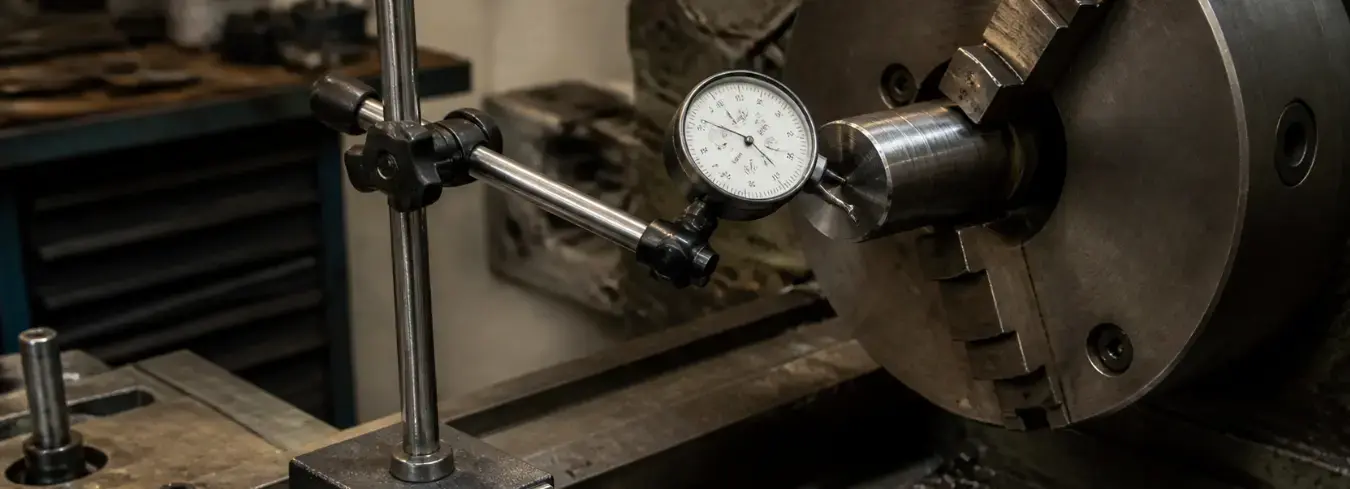
Most dial indicator errors are not caused by the instrument. They are caused by a bad setup.
A loose arm joint. A contact point touching the surface at the wrong angle. A magnetic base sitting on a thin layer of cutting oil. Any of these will give you a reading you cannot trust. The indicator only shows what its contact point is feeling. If the stand moves 0.03 mm during measurement, that movement adds to your reading.
This guide covers how to set up a dial gauge with a magnetic base stand correctly, how to read it, and how to avoid the mistakes that produce wrong numbers.
What a Dial Indicator Measures
A dial indicator measures small linear movement. The contact point at the tip of the instrument moves in and out. That movement drives a gear train inside the body, which rotates the needle on the dial face.
On a standard metric dial gauge, one full revolution of the needle equals 1 mm of contact point travel. The dial is marked in 0.01 mm divisions. The small sub-dial (the revolution counter) shows how many full millimetres the contact point has moved. Always check the sub-dial too when measuring anything larger than 1 mm.
For tighter tolerances, tenth indicators read in 0.001 mm increments. These are used for precision grinding, tight-tolerance boring, and inspection work where 0.01 mm is not fine enough.
Common uses in UAE machine shops:
- Checking lathe chuck runout before turning a precision part
- Dialling in a 4-jaw chuck to 0.01 mm or better
- Checking that a milling vice jaw is parallel to the table
- Indicating a workpiece position on a milling table
- Measuring shaft play, bearing clearance, and spindle end float
- Verifying surface flatness and parallelism after machining
How the Magnetic Stand Works
The magnetic base holds the indicator arm in position while you measure. It mounts on any steel or cast iron surface: the lathe cross-slide, milling table, machine body, or surface plate.
Inside the base is a permanent magnet. The on/off lever rotates the magnet assembly. In the OFF position, the poles cancel each other and the base lifts freely. Switch it ON and the poles face the base plate, locking the stand firmly to the surface.
A good stand holds 50 to 120 kg on a clean, flat surface. That force drops sharply on a dirty or rough surface. This is why many measurement errors come from the stand, not the indicator. A base that looks locked can still shift slightly under measurement pressure if the surface is oily or pitted.
The arm attached to the base has two or three sections with clamping joints. The indicator mounts at the end, usually through an 8 mm stem clamp. Keep the arm as short and compact as possible. A long, extended arm flexes more and gives less reliable readings.
For precise measurement in UAE workshops, stand quality matters as much as indicator brand. If you need a magnetic stand in the UAE, check the holding force rating against your machine size before buying.
How to Set Up a Dial Indicator Step by Step
Step 1: Clean the Mounting Surface
Wipe the surface where the magnetic base will sit. Remove cutting oil, chips, and coolant. A thin oil film between the magnet and the steel reduces holding force significantly. A chip or burr under the base lifts one corner of the magnet and reduces contact area.
This takes thirty seconds. It prevents the most common cause of bad readings.
Step 2: Place the Base (Magnet OFF)
Place the base on the clean surface with the magnet switched OFF. Position it as close as possible to where you need to measure. A shorter arm reach means a more rigid setup and a more reliable reading.
Do not switch the magnet on yet. You still need to move the base while setting arm position.
Step 3: Extend the Arm Toward the Workpiece
Loosen all the arm joints. Extend the arm roughly toward the measurement point. Do not tighten anything yet. You are getting into position, not making final adjustments.
For lathe runout, position the base on the cross-slide or toolpost. The contact point should end up near the chuck face, pointing at the outer diameter of the workpiece.
Step 4: Mount the Dial Indicator
Slide the indicator stem into the clamp at the end of the arm. Standard stem diameter is 8 mm on most metric dial gauges. Confirm the clamp size matches. Orient the dial face so you can read it clearly while rotating the spindle. Do not fully tighten the stem clamp yet.
Step 5: Bring the Contact Point to the Surface
Move the arm until the contact point just touches the workpiece surface. For lathe runout, it should point directly at the spindle centreline, perpendicular to the surface.
This angle matters. If the plunger approaches at an angle, it only reads part of the true movement. This is called cosine error. A 10-degree angle causes about 1.5% error. A 30-degree angle causes about 13% error. Keep the plunger as close to perpendicular as possible.
Step 6: Pre-load the Contact Point
Push the contact point into the surface until the needle moves 0.5 to 1 mm past zero. This is called pre-load.
Without pre-load, the contact point lifts off the surface at the low point of the measurement. When that happens, the reading drops to the mechanical stop and the result is completely wrong. Pre-load keeps the tip in contact through the full range of surface movement.
This is the step most people skip. It is the reason most bad runout readings happen.
Step 7: Lock the Arm and Switch the Magnet ON
Tighten the arm joints firmly, starting from the base end toward the indicator. Then switch the magnet ON.
After locking, check the pre-load again. Tightening joints often shifts the contact point slightly. If the needle has moved more than 0.2 mm from your pre-load position, adjust and re-lock.
Step 8: Zero the Bezel
Rotate the outer bezel ring until the zero line aligns with the needle. This sets your reference point.
For runout measurement, zero the bezel at the lowest point of the surface. Rotate the spindle by hand until you find the lowest needle position. Set zero there. Then continue rotating. The highest reading the needle reaches in one full turn is your Total Indicator Reading (TIR).
How to Read the Dial Indicator
Reading TIR (Total Indicator Reading)
TIR is the full range of needle movement across one complete spindle rotation, not a single point reading.
Rotate the spindle slowly through 360 degrees. Watch the needle move between the high and low points. The difference between the highest and lowest reading is your TIR, which equals total runout.
If you zeroed at the low point, the needle swings only positive, and the peak reading directly gives you the TIR.
Reading the Revolution Counter
The small sub-dial records full revolutions of the main needle. Each unit equals 1 mm of contact point travel.
For runout checks, the counter rarely moves because you are working within a fraction of 1 mm. But for measuring steps, travel distances, or bore depths, always read the counter first and add the main dial reading to it. Forgetting the counter produces a reading that is exactly 1 mm too small.
Checking Lathe Chuck Runout
Mount the magnetic stand on the lathe cross-slide or toolpost. Position the contact point on the outer diameter of a test bar held in the chuck, close to the chuck face. Pre-load 0.5 mm. Lock the arm. Zero the bezel at the low point.
Rotate the chuck by hand through one full turn. The highest reading the needle reaches is your TIR.
What the TIR tells you:
TIR Reading | Condition |
Below 0.05 mm | Good, acceptable for precision turning |
0.05 to 0.15 mm | Normal for a quality 3-jaw chuck |
0.15 to 0.25 mm | Scroll wear, watch effect on part accuracy |
Above 0.25 mm | Chuck needs attention or replacement |
Below 0.01 mm | 4-jaw chuck dialled in, ready for precision work |
For dial gauges and magnetic stands in the UAE, Insize and Vertex instruments are available with calibration certificates for documented quality systems. Workshops needing Mitutoyo dial indicators in Dubai can find the full range including 0.01 mm and 0.001 mm resolution models.
Dialling In a 4-Jaw Chuck
The 4-jaw chuck holds any shape and gives much higher accuracy than a 3-jaw. But every workpiece must be dialled in manually using a dial indicator.
For a full comparison of 3-jaw vs 4-jaw chuck selection, see the guide on lathe chuck differences and accuracy. Short version: any concentricity requirement better than 0.05 mm goes in the 4-jaw.
The process:
- Mount the workpiece roughly by eye. All four jaws hand-tight.
- Set up the dial indicator on the outer surface. Zero the bezel.
- Rotate the spindle one full turn. Note the high point and the low point.
- Loosen the jaw at the high point. Tighten the jaw directly opposite. Move the part halfway toward zero on this axis.
- Rotate 90 degrees. Repeat the same adjustment on the other pair of jaws.
- Go back to step 3. Adjusting one pair disturbs the other axis slightly. Keep iterating until the needle shows less than 0.01 mm for a full rotation.
- Tighten all four jaws firmly. Recheck. Correct any small shift from tightening.
With practice, 0.01 mm TIR on a round part takes three to four minutes.
Using a Dial Indicator on a Milling Machine
On a milling machine, the magnetic base clamps to the spindle quill housing or machine column. Two setups are common.
Squaring the vice jaw to the table
Touch the contact point to the fixed jaw of the vice. Move the table in the X-axis. Any needle movement means the jaw is not parallel to table travel. Tap the vice body to correct it. Repeat until the needle holds steady across the full jaw length.
Positioning a workpiece for boring
Before boring a hole to a precise location, use the indicator to locate the workpiece. Touch a reference face of the part. Move the table to bring the surface into alignment, zeroing the indicator in each axis. The part is now positioned correctly before the boring bar enters.
For milling and precision inspection work, calibrated measuring instruments from authorised UAE dealers give you traceable, reliable reference readings.
Dial Indicator vs Dial Test Indicator
These are two different tools. Knowing the difference helps you pick the right one.
A dial indicator (also called a plunger indicator or dial gauge) has a contact point that moves straight in and out along a plunger axis. It is the standard choice for runout checking, surface parallelism, and most lathe and milling setups.
A dial test indicator (DTI or lever indicator) has a pivoting stylus arm that swings sideways. It is smaller and can reach into places a plunger indicator cannot: undercuts, internal bores, narrow slots. Use a DTI for indicating bores and internal surfaces.
Both come in 0.01 mm and 0.001 mm resolution versions.
Common Mistakes to Avoid While Using a Dial Indicator
- Dirty magnetic base surface
Oil or chips under the base reduce holding force and let the stand shift during measurement. Clean the surface before every setup. A shifted base adds error to every reading.
- No pre-load
Without pre-load, the contact point loses contact at the low point of the surface. The needle drops to the mechanical stop and the reading is useless. Always pre-load 0.5 to 1 mm.
- Wrong contact point angle
The plunger should be perpendicular to the measured surface. An angled approach gives a smaller reading than the true movement. For lathe runout, the tip must point directly at the spindle centreline.
- Measuring too far from the chuck
For runout, measure as close to the chuck face as possible. Any angular error in the chuck amplifies along the length of a test bar. At 100 mm from the chuck, apparent runout is larger than the actual chuck error.
- Forgetting the revolution counter
For any measurement above 1 mm, ignoring the sub-dial gives a reading that is 1 mm short per revolution missed. Read the counter first, then add the main dial.
- Locking joints before positioning
Tightening a joint shifts the contact point. Set your position and pre-load first. Then lock, starting from the base end toward the indicator.
Conclusion
A dial indicator gives you numbers you can trust only when the setup is right. Clean the magnetic base surface. Pre-load the contact point. Keep the plunger perpendicular to the surface. Read TIR, not a single point. Get these four things right and the indicator will never let you down.
For Insize and Mitutoyo dial indicators, magnetic base stands, and precision measuring instruments in the UAE, visit arhtrd.com, authorised measuring instruments supplier in Dubai.
What is the difference between a dial indicator and a dial gauge?
They are the same instrument. “Dial gauge” is the common term in the UAE and most of the world. “Dial indicator” is used more in technical documentation. Both refer to the plunger-type tool with a circular dial face.
Why do I get different readings every time I set up the indicator?
This almost always comes from an unlocked arm joint, no pre-load, a dirty magnetic base surface, or the contact point touching the surface at a different angle each time. Fix each of these in order and the readings will be consistent.
Can a dial indicator measure inside a bore?
Not directly. For internal bores, use a bore gauge. Set the bore gauge inside the bore, then use the dial indicator to read the bore gauge. The indicator converts the bore gauge movement into a readable measurement.
How do I know if my indicator needs calibration?
Check it against a precision gauge block of known size. Run the contact point from zero to the block thickness and compare the reading to the actual dimension. If the indicator reads consistently high or low, it needs recalibration.
What holding force do I need in a magnetic stand?
For standard lathe and milling work, 60 to 80 kg holding force is sufficient. For larger machines or a fully extended arm, choose a stand rated at 100 kg or more. Rated force assumes a clean, flat, smooth surface. On a rough or pitted surface, actual holding force is much lower.
Where can I buy dial indicators and magnetic stands in Dubai?
Insize, Mitutoyo, and Vertex dial indicators with matching magnetic base stands are available through authorised measuring instrument dealers in the UAE. Confirm resolution and travel range before ordering. Ask for calibration documentation if your quality system requires it.